The media access control sublayer is responsible for allocating and managing the resources needed to transmit data over a network.
The Logical Link Control (LLC) sublayer is a crucial component of the Data Link layer responsible for handling multiplexing, managing the flow of data among different applications and services. It ensures the proper and reliable transmission of data between the sender and receiver.
The Media Access Control (MAC) sublayer is another essential sublayer within the Data Link layer. Its primary functions include managing the interaction of devices in a network, addressing frames to facilitate proper delivery, and controlling access to the physical communication media. The MAC sublayer plays a key role in coordinating the use of shared communication channels and preventing data collisions.
In broadcast or multicast network, single channel is shared by several stations. This channel can be allocated only to one transmitting user at a time.
There are two different methods of channel allocation :
In static channel allocation method, a single channel is divided amongst various users either on the basis of frequency or time. Therefore they either uses FDM or TDM. In FDM, fixed frequency is statically assigned to each user, whereas in TDM, a fixed time slot or slice is allocated to each user.
In case of FDM, if there are n users, it means there will be n frequency bands. If at a particular time, just two or three users are transmitting data then majority of the channel bandwidth is wasted. Also, in TDM if user does not transmit data druing its time slot, it goes empty leading to wastage of channel time.
And if more than n users want to use channel, some of the users will be denied the access because of lack of bandwidth.
In dynamic channel allocation method, none of the users in assigned fixed frequency or fixed time slot. Following assumpotions are made in order to implement this method :
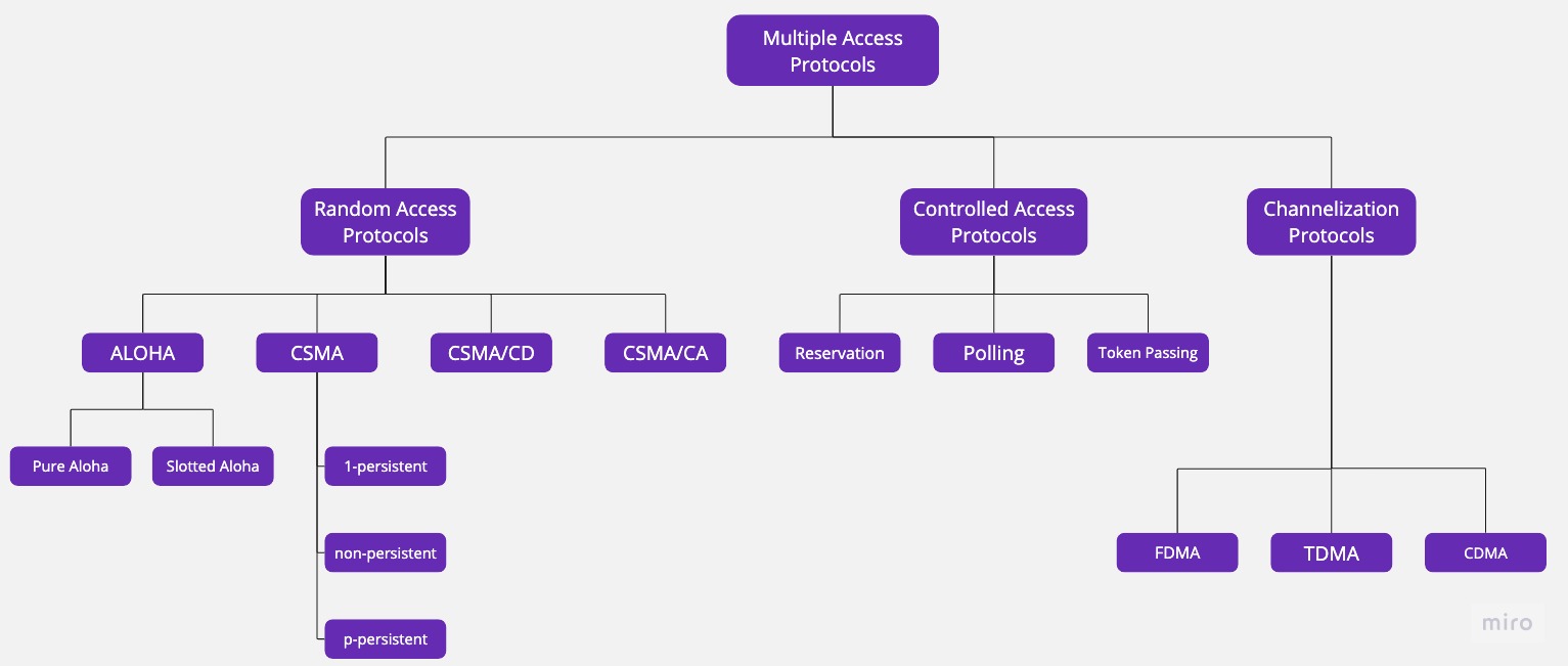
Many formal protocols have been defined to handle the access to shared link.
They are organised in groups :
It is also known as contention method.
In this method, there is no control station or administrative, so any station can send the data when the channel is idle. It is called random access because ther eisno scheduled time for a station to transmit and the stations can transmit in random order.
The various random access methods are : ALOHA, CSMA, CSMA/CD and CSMA/CA.
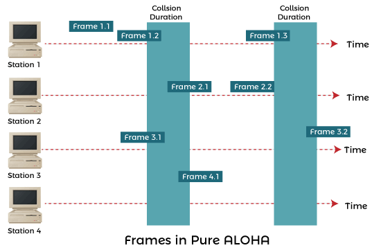
In this method, stations share a common channel and when two stations transmit simultaneously then collision occures and frames are destroyed. It was used for ground based radio broadcasting.
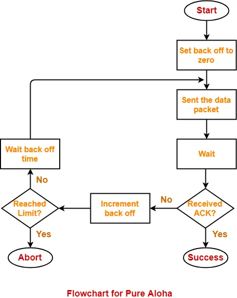
In pure aloha, whenever any station transmits a frame, it expects the acknowledgement from the receiver. And if collision happen, it retransmits the frame after waiting for random time.
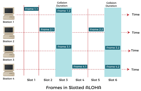
In slotted aloha, the time of the shared channel is divided into discrete intervals called slots. The stations can send a frame only at the beginning of the slot and only one frame is sent in each slot. Thats how slotted aloha reduces the possibilites of collision than pure aloha.
In CSMA, the station senses the carrier or channel before transmitting frame. Although it reduces the chances of collision but it cannot eliminate it completely. The chances of collision still exist because of propagation delay.
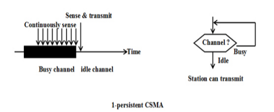
In this method, station that wants to transmit data continuously senses the channel and when it detects an idle-channel, it immmediately transmits the frame with probability 1.
This method has the highest chance of collision because two or more stations may find channel to be idle at the same time and transmit their frames.
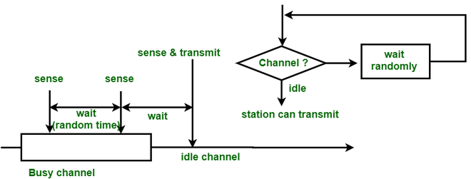
In this method, station senses the carrier or channel. If channel is idle, it sends immmediately. If the channel is busy, it waits a random amount of time and then senses the channel again.
It reduces the efficiency of network because the channel remains idle when there may be stations with frames to send.
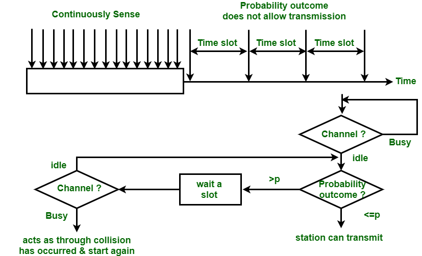
This method is used when channel has time slots such that the time slot duration is equal to ro greater than the maximum propagation delay time.
In this method, station continuously senses the channel and when the channel is idle it sends one frame with probability p and wait for a time slot and then again sense the channel and if channel is idle then transmits next frame.
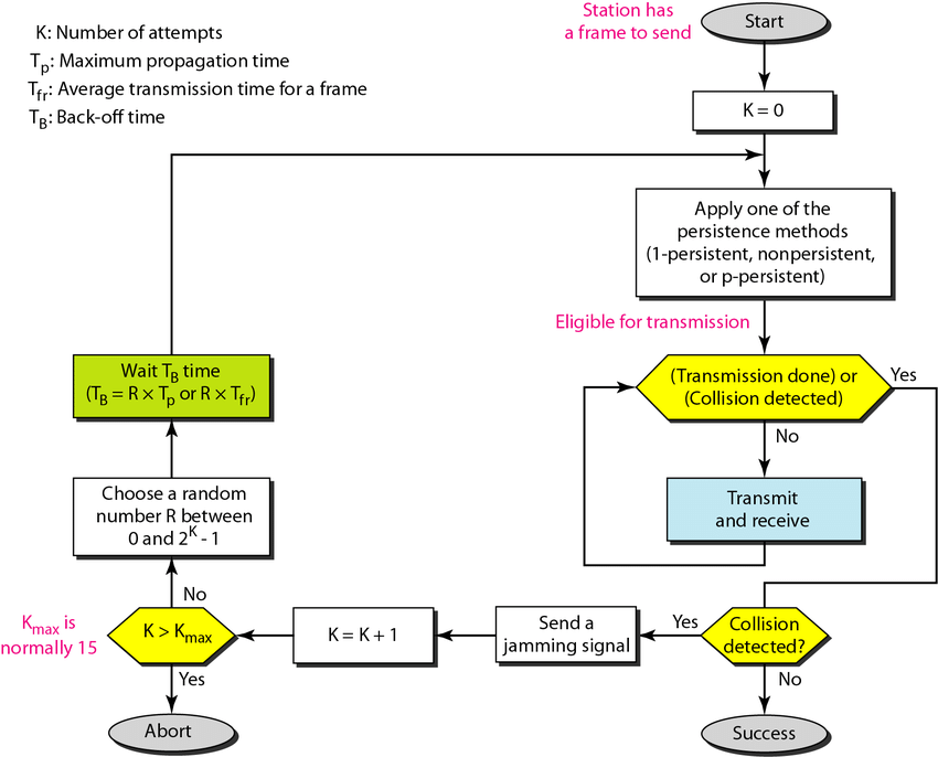
This is same as CSMA but the additional feature in CSMA/CA is that the stations can detect the collisions. A station monitors the medium after it sends a frame to see if the transmission was successful. If so, the station is finished. If collision is detected, the station aborts its transmission and waits for predetermined amount of time and then sends its data again.
As soon as a collision id detected, the transmittion station releases a jam signal. Jam signal will alert the other stations. The stations are not supposed to transmit immediately after teh collision has occured. After some back-off delay time the stations will retry the transmission and if collision occurs again then the back off delay time is increased progressively.
This method only works for wired networks because it is difficult to detect collisions in wireless medium.
This protocol is used in wireless networks because they cannot detect the collision so the only is collision avoidance.
It avoids the collisions using three basic techniques :
Interframe spacing is a technique used to prevent collisions by ensuring that the time between two frames is greater than the maximum propagation delay time. It introduces a gap between frames to allow for proper transmission and reception.
The contention window is a technique used to prevent collisions by ensuring that the time between two frames is less than the maximum propagation delay time. It involves randomizing the waiting time before transmitting a frame to reduce the chances of collisions.
Acknowledgements are a technique used to prevent collisions by ensuring that the time between two frames is less than the maximum propagation delay time. It involves the receiver sending an acknowledgment signal to the sender to confirm successful reception of a frame.
In this method, stations consult each other to find which station has a right to send
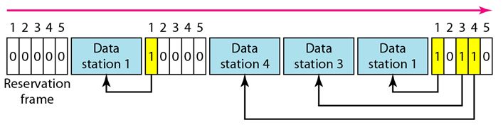
Reservation is a technique used in access control protocols where a device reserves a specific time slot or bandwidth in advance to transmit its data. This ensures that the reserved resources are exclusively available for the transmitting device during the reserved time period, reducing the chances of collisions.
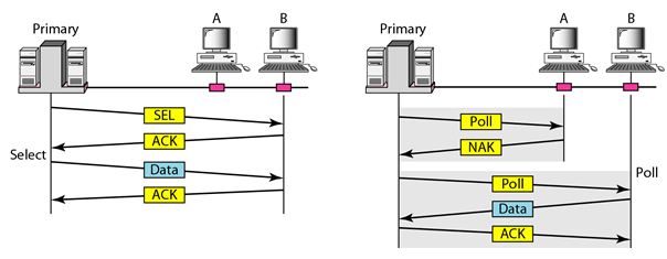
Polling is a technique used in access control protocols where a central device, known as the master, controls the communication by sequentially polling the connected devices to check if they have data to transmit. The master device grants permission to the polled device to transmit its data, ensuring orderly access to the communication channel.
Token passing is an example of a centralized access control protocol. In a token passing network, a token circulates among devices, granting the device holding the token the right to transmit data. This ensures controlled and orderly access to the channel.
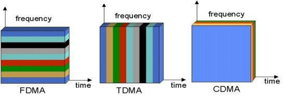
Channelization is a multiple access method in which the available bandwidth of a link is shared in time, frequency or through code between different stations.
FDMA is a channelization protocol that divides the available frequency spectrum into multiple non-overlapping frequency bands. Each device is assigned a specific frequency band for communication, ensuring that devices operate on separate frequencies and do not interfere with each other.
TDMA is a channelization protocol that divides the available time slots within a given time frame into multiple time slots. Each device is assigned a specific time slot for communication, allowing devices to transmit data sequentially within their allocated time slots.
CDMA is a channelization protocol that assigns a unique code to each device. Instead of dividing the frequency or time, CDMA allows multiple devices to transmit simultaneously by encoding their data using different codes. The receiver can then decode the specific data intended for it using the corresponding code.
The Institution of Electrical and Electronic Engineers (IEEE) has developed several standards for LANs.
802.1 Network management and Internetworking
802.2 Logical Link Control
802.3 Ethernet or CSMA/CD
802.4 Token Bus
802.5 Token Ring
802.6 MAN or Distributes Queue Dual Bus (DQDB)
802.7 Band pass Technical Advisory Group
802.8 Fiber Optic Technical Advisory Group
802.9 Integrated Data and Voice Network
802.10 Security Working Group
802.11 Wireless LAN
Introduced commercially in 1980 and first standardized as IEEE 802.3 in 1983, Ethernet has undergone numerous refinements to support higher bit rates and extended link distances, replacing other LAN technologies like token ring, FDDI, and ARCNET.
Initially utilizing coaxial cables as a shared medium, modern Ethernet variations have adopted twisted pair and fiber optic links, coupled with hubs or switches, to facilitate communication and data transfer within LANs and MANs.
Over its evolution, Ethernet has boosted data transfer rates from an initial 2.94 Mbit/s to a remarkable 100 Gbit/s, offering several wirings and signaling options as part of the OSI physical layer in sync with Ethernet standards.
Data is segmented into "frames" that carry source and destination addresses along with errorchecking data, facilitating the detection and discarding of damaged frames, and enabling higherlayer protocols to trigger the retransmission of lost frames.
Wi-Fi, a wireless protocol standardized as IEEE 802.11, serves as a prominent alternative to Ethernet in contemporary Local Area Networks (LANs).
Operates using a Bus topology, connecting all devices to a common communication line; acknowledgments are not inherently used, but can be incorporated as data packets if necessary; utilizes Manchester encoding techniques for data transmission.
Connectionless and Unreliable Service :
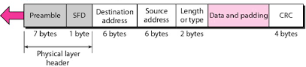
Preamble: It is the starting field that provides alert and timing pulse for transmission. In case of classic Ethernet it is an 8 byte field and in case of IEEE 802.3 it is of 7 bytes.
Start of Frame Delimiter: It is a 1 byte field in a IEEE 802.3 frame that contains an alternating pattern of ones and zeros ending with two ones.
Destination Address: It is a 6 byte field containing physical address of destination stations.
Source Address: It is a 6 byte field containing the physical address of the sending station.
Length: It a 7 bytes field that stores the number of bytes in the data field.
Data: This is a variable sized field carries the data from the upper layers. The maximum size of data field is 1500 bytes.
Padding: This is added to the data to bring its length to the minimum requirement of 46 bytes.
CRC: CRC stands for cyclic redundancy check. It contains the error detection information.